-40%
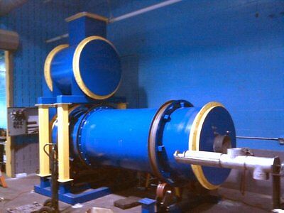
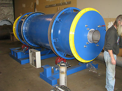
500 lb/hr Rotary Kiln Dryer Gasifier Incinerator
$ 42240
- Description
- Size Guide
Description
TYPICAL HTT SYSTEM DESCRIPTION1.1A
Manual Charging System
With the smaller systems, material will be fed manually through a charging door.
This door will be interlocked with the burner and air system to prevent improper operation. A loading door is provided as well as ash cleanout doors in both the primary and afterburner chambers.
1.1B
Manual and Hydraulic Ram Charger (RCM-RCH)Optional
Solid waste will be fed to the Ignition Chamber with a Ram Charger. Waste will be deposited into a feed hopper. The ram charger will accept pallets, paper, cardboard, wooden crates, etc.
The charger will store one load of the materials and feed them at a controlled rate.
Temperature sensors will limit the feed system thus maintaining a constant burn rate. The compacted waste in the charger will isolate the chamber from the Ignition Chamber thereby maintaining proper flow and eliminating the possibility of ignition of the waste within the feeder. Thermocouples interlocked to the control panel and the feeder will prevent operation except at pre-selected temperatures on the control panel.
Temperature interlocks on the feeder will also detect fires and spray them with water automatically should it occur.
1.2 Screw Feed System (SF)Option
Waste will be fed to the Ignition chamber through around access door. Shredded material shall be loaded into a screw feed hopper with water-cooled nose piece. The feed hopper shall be complete with heavy dutyshaft and screw, housing, and reduced motor drive. Temperature sensors will limit the feed system thus maintaining a constant burn rate. Thermocouples interlocked to the control panel and the feeder will prevent operation except at set temperatures on the control panel. The tip includes a 304 SS water-cooled jacket
1.3 Primary Ignition Chamber – Rotary Kiln
The Primary chamber is used to burn waste material and shall be constructed of carbon steel plate.
The chamber shall be complete with the required structural supports, support channels, and flanged connections.
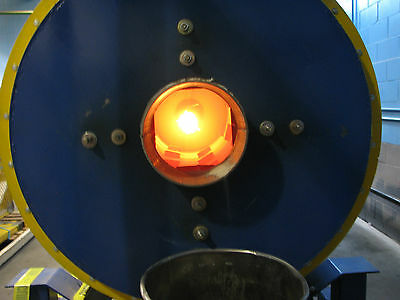
This section contains the inspection door, burner, and connecting duct to the secondary chamber.
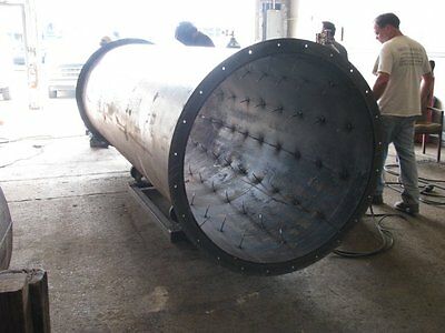
The chamber shall be lined with a combination of both insulating and hard faced refractory materials.
The refractory shall be suitably supported with stainless steel anchors for long life.
The chamber shall be complete with access doors for inspection and maintenance. All inner steel surfaces will be coated with an acid resistant epoxy paint.
At the duct outlet connection shall be air nozzles connected to a blower.
As the combustion rate of the material increases, the damper is opened thus maintaining a proper air ratio for complete combustion of the smoke and particulate. The materials to be burned are charged into the refractory-lined primary chamber, which has been preheated to normal operating temperature.
The burner heats the material and the organic components are converted to volatilized gases.
The action of the burner and use of fuel is normally intermittent, but depends upon the moisture content of organic materials to be consumed.
The smoke (unconsumed organics) and gases are drawn into a second chamber for final thermal oxidation.
The ash remains in the primary chamber and settles to the bottom. An access door is provided for ash removal. The thick refractory lining retains the heat while over-fire air supports the combustion from the other side. A controlled air condition is maintained and the reduction of the waste product is semi pyrolytic. Non-combustible materials and ash collect on the hearth and are manually removed from the chamber each morning prior to startup.
During normal operation no ash will have to be handled, preventing a potential health hazard. The ash shall drop out of the primary chamber into an ash collection space below the hearth. The ash shall be cooled with air at the end of the burning cycle prior to removal.
Design and Material Specifications
- Our standard design criteria exceed those of our competition.
Shell material is 0.25-0.375 in (7.2 mm)carbon steel plate.
Hearth area loading is 15 #/ft2 (200kg/m2/hr)
Afterburner sizing is 1 sec residence time,
166 ft3/ton/hr (5.28 m3/tonne/hr) at6,000 btu/lb
Primary chamber insulation is 6.5 in
Breaching chamber insulation is 6.5 in
Secondary chamber insulation is 6.5 in
1.4 Rotary Kiln Designs
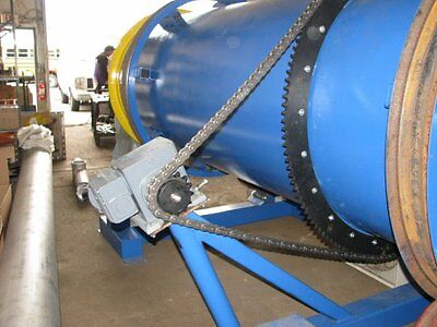
RotaryKiln Continuous Operation Design (500-4000 lbs./hr)
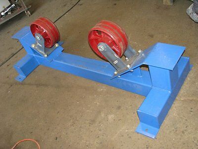
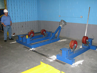
The rotating chamber is proven to be one of the best available technologies to burn solid materials and sludge. Contaminated materials such as sludge and soil can be heated to drive off contaminates and the chemical vapors produced are destroyed in the afterburner chamber. The hard refractory used in the Rotary Kiln typically would be field installed due to the weight problems of shipping.The weight of hard refractory is 160 pounds per cubic foot. The complete lined chamber of the larger systems can weigh over 50 tons.
Connected to the primary chamber shall be a stationary mating section. This section contains the inspection door, blast gate peep sight, burner, and connecting duct to the secondary chamber. Both the burning chamber and a stationary chamber shall be mounted on a single trailer. At the chamber to the outlet connection shall be air nozzles connected to a high-pressure blower with actuated damper. As the combustion rate of the material increases, the damper is opened thus maintaining a proper air ratio for complete combustion of the smoke and particulate.
1.5 Secondary Combustion Chamber
The secondary chamber shall be constructed of carbon steel plate and is located next to or above the primary chamber. The chamber shall be complete with the required structural supports, and flanged connections.
The chamber shall be lined with a combination of both insulating and hard faced refractory materials.
The refractory shall be suitably supported with stainless steel anchors for long life.
The chamber shall be complete with access doors for inspection and maintenance.
The Secondary Combustion Chamber operates at a higher temperature than the Primary Chamber and consumes the gases, smoke, and particulate.
The volatile products resulting from the thermal reduction process are drawn into the combustion chamber to be further oxidized.
The burner is positioned so that the incoming gases and particulate pass through the flame and are ignited.
The direction of the flame assures a swirling, vortex action providing maximum turbulence and residence time to the burning mass.
High Temperature Design Option
Some applications will require higher operating temperatures. For this reason we have designed options for these requirements. The second chamber would normally operate at 950-1000C and can be resized for 1200C at a 1-2 second residence time. The first chamber would operate at 750-800C. This temperature is high enough for sterilization and thermal destruction of the waste materials.
1.6 Burners
The Solid Waste Incineration System will be equipped with two (2) Natural Gas/LPG or #2fuel oil Burners with flame safeties.
The burners will be mounted to the outer shells of both the primary and afterburner chambers and are directed to assure required mixing.
Also included will be complete FM fuel valve trains.
l.7 Controls
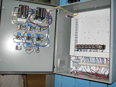
The temperature controllers shall monitor the system temperatures and control feedrates and charger functions, external equipment conditions, and safeties. The system is designed to permit the proper and safe operation of the unit and to provide the operator with various options to broaden the versatility of the unit.
The control panel includes the various electrical controls to assure a safe start-up and pre-heat of the chambers and operation of the system.
Both under and over temperature limit set point circuits are interlocked with the feeding mechanism to assure control in feeding waste materials.
The system is designed to interlock feeding of charges until the conditions of both chambers are brought up to predefined temperature levels.
The feeding process will also stop if, during operation, conditions in any of the combustion chambers deviate from these preestablished conditions.
Adjusting the fuel-to-air ratio according to temperature monitors in the designated flue gas flow areas controls operating temperatures in both chambers.
Temperature is sensed by Chromel Alumel TypeK thermocouples, which are connected to the system temperature controls, which regulate the auxiliary fuel.
l.8 Insulated High Temperature Stack Sections (HTS) Option
This item includes 96” sections of refractory lined stack.
Stack shall be constructed of 0.25 in rolled carbon steel and shall include 6 in of ceramic fiber refractory insulation.
Sections are flanged at both ends for ease of installation and future modifications.
1.9 Packed Tower Scrubber (PTS) Option
Applications where plastics and chlorinated solvents are present will produce free Cl in the stack exhaust. When cooled, the Cl it will combine with water to form HCl, a very corrosive, hazardous and dangerous acid. A scrubber can be added to the system to remove HCl. The Scrubber will clean the gases of fumes before being discharged into the atmosphere.
The gases contact the scrubber water to condense the fumes and wet the particles while cleaning the interior walls of the housing.
The scrubber shall be constructed of FRP or 316L SS and will include a quenching section, venturi, circulation pump, filler valve, level sensor, liquid storage,packed tower, and demister pad.
All components shall be skid mounted for ease of assembly. A mixing section or packed tower accelerates the gas flow and maximizes the collection of the pollutants.
The demister separation section removes ultra fine droplets and particles prior to being drawn to the atmosphere.
1.10 Data Logger (DL) Option
Package may include a data logger.
Recorder shall accept T/C, MA, or DC inputs for required sensors.
These will accept the inputs from the optional monitors.
The panel shall be provided with Nema 4 control switches, indication lights, and terminal strip contactors.
1.11 304 Stainless Steel Stack (SSS) Option
The Dilution Air Stack is 11 ga. 304 Stainless Steel and includes (1) transition section and one (1) 8 ft. section of stack.
Stack shall be constructed of 0.125” rolled stainless steel and shall include flanges at both ends.
Sections are flanged for ease of installation and future modifications.
Storage brackets may be provided on the top of the unit for use during shipment.
HiTemp Tech Corp
14 Sandra Rd, Ringoes,NJ
08551
908-500-7500
[email protected]
www.thermcat.net
